1. Bench pickup check
Start with representative parts, including the worst expected surface condition. Check pickup contact, peel risk, air gap, and any stacked-part behavior before approving the gripper concept.
Engineering review for magnetic circuit assumptions, contact area, workpiece thickness, and safety factor.
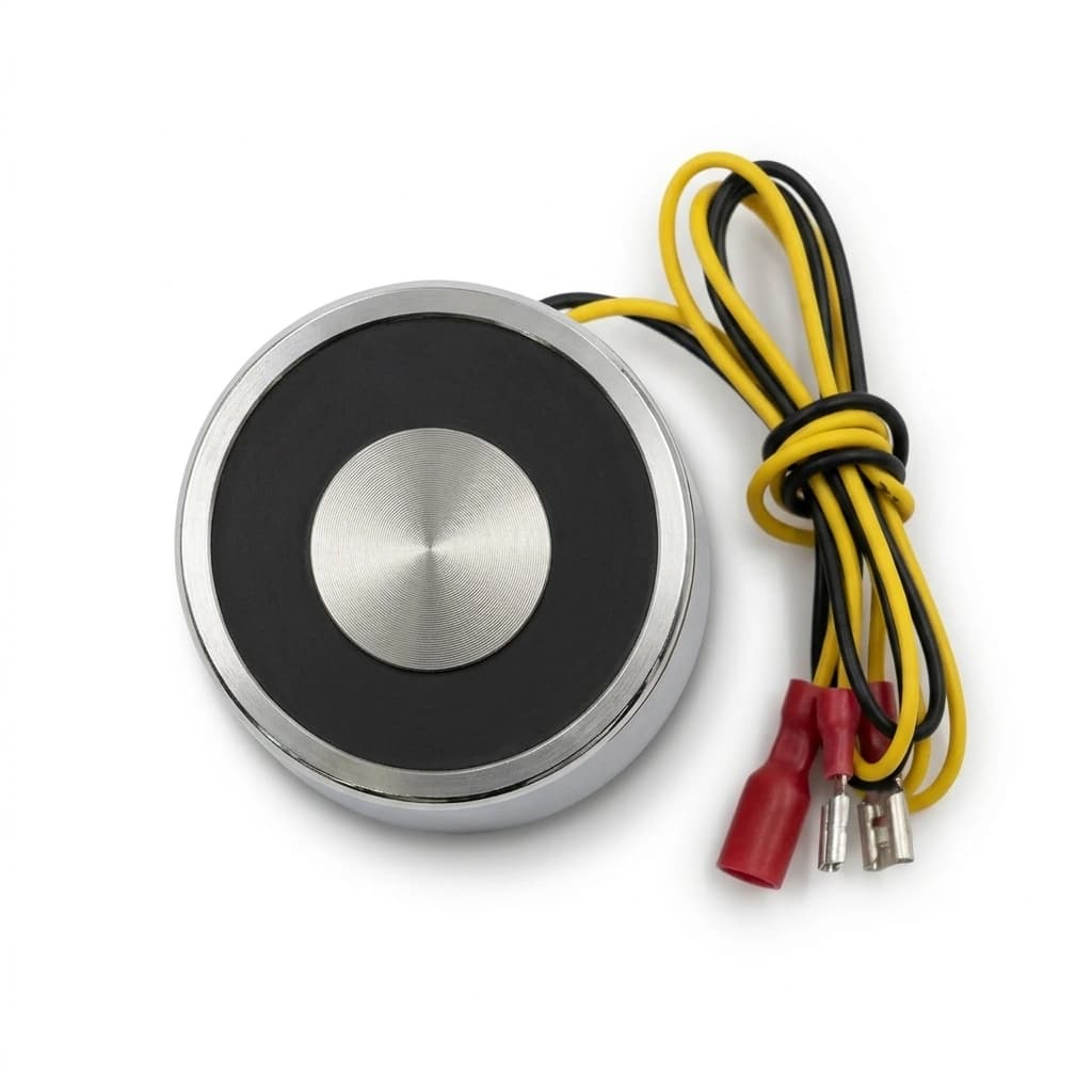
Treat holding force and pole layout review as a complete handling decision, not a stand-alone magnet purchase. The right choice depends on whether the workpiece can be held magnetically, whether the robot motion keeps enough margin, whether the part releases cleanly, and whether the installation scope is clear enough for quotation.
Buyer fit: For teams that need a magnetic gripper sized around real parts instead of catalog assumptions. Before comparing price, align the practical constraints below so the quote reflects the real automation cell instead of a generic catalog condition.
| Decision Area | Buyer Question | Practical Evidence |
|---|---|---|
| Workpiece fit | Can the magnetic poles contact enough real surface area under production conditions? | Send workpiece material grade, magnetic permeability class, and heat treatment state plus photos or drawings of the pickup face. |
| Motion margin | Will the gripper hold through acceleration, rotation, off center pickup, and stop conditions? | Review force margin because the right margin depends on workpiece, motion, orientation, and risk level. |
| Release behavior | Can the part release within the placement tolerance without residual magnetism, double pickup, or stack disturbance? | Define sample acceptance criteria around force margin and record the release test result before batch release. |
| Interface scope | Are the flange, adapter, cable, connector, controller, and documentation assumptions included in the same RFQ? | Confirm material and magnetic permeability and list any custom mounting or control requirements before PO release. |
Start with representative parts, including the worst expected surface condition. Check pickup contact, peel risk, air gap, and any stacked-part behavior before approving the gripper concept.
Test the planned orientation, acceleration, tool center, cable route, and stop assumptions. A static lift is not enough when the cell includes fast motion or rotated handling.
Measure release timing, residual magnetism, placement tolerance, and repeatability across a small run. Use the result to freeze pole layout, interface, and quality-control notes.
The most common sourcing mistake is treating holding force as a fixed catalog value. In practice, catalog holding force assumes flat, clean, thick mild steel — production parts differ. Always base force calculations on the actual workpiece material, surface condition, and contact geometry, then add the agreed safety factor. Another common issue is that pole layout is optimized for one part but a second sku has a different contact pattern. Map all workpiece variants that the same gripper must handle and test the weakest variant before freezing the pole layout.
For a quote that can move from engineering review to procurement, include the workpiece file set, automation interface, cycle target, release requirement, quantity, destination, and any custom packaging or documentation needs. If those values are not final, mark them as assumptions so the quotation can separate confirmed scope from validation-dependent scope.
| Program Metric | Typical Range | Procurement Value |
|---|---|---|
| Force margin | Defined by application review and sample tests | The right margin depends on workpiece, motion, orientation, and risk level. |
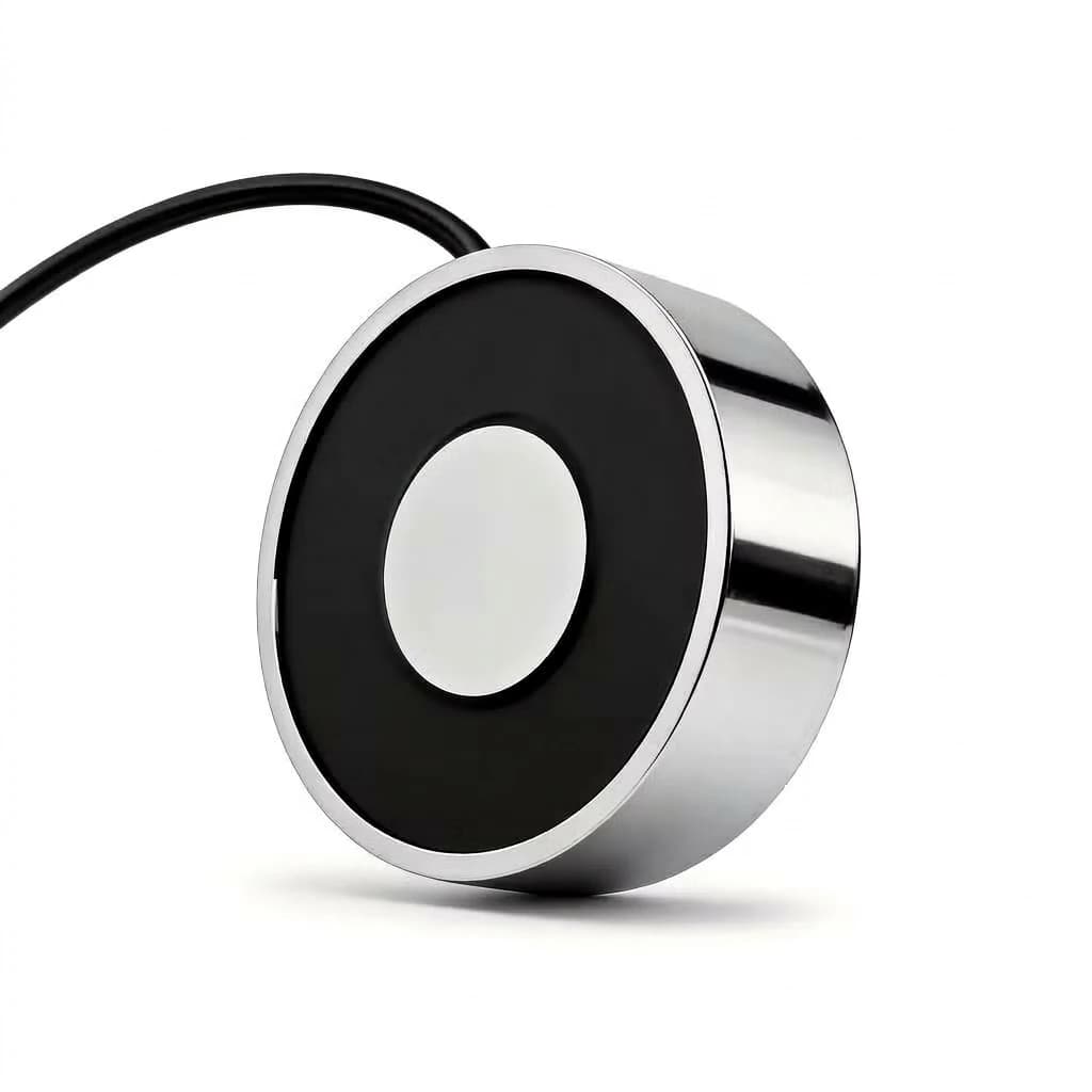
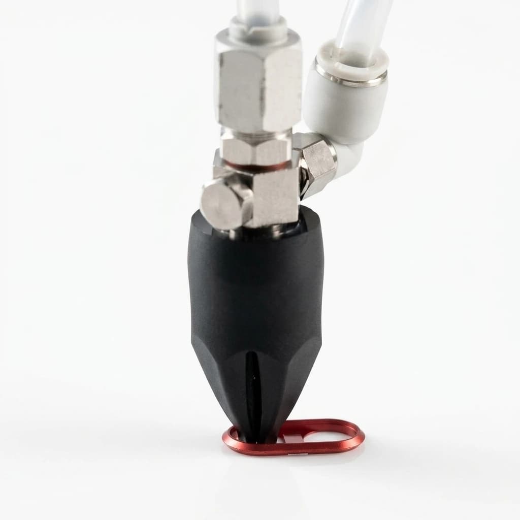
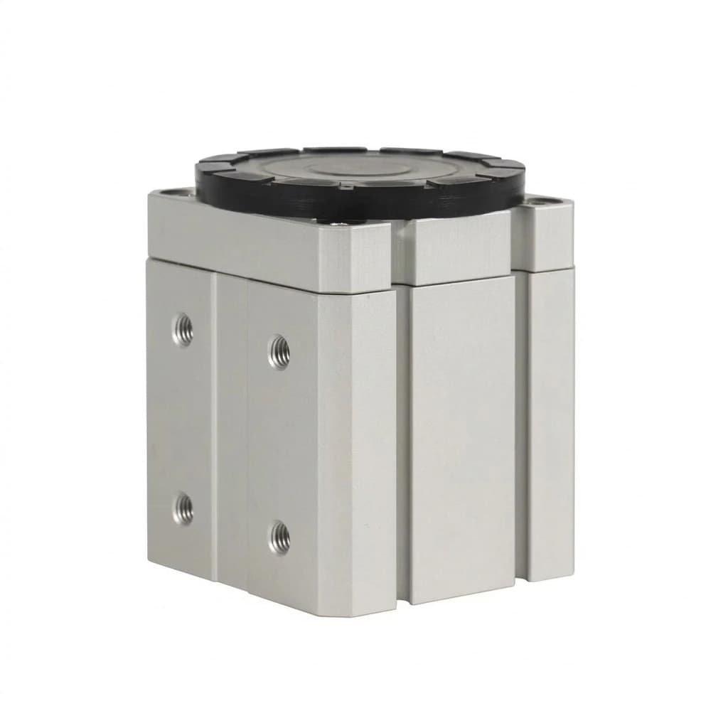
Catalog values are measured on thick, flat, clean mild steel under static conditions. Real workpieces have air gaps from coating, oil, burrs, curvature, and thinner cross-sections that reduce the effective force.
Pole count depends on the workpiece size, contact area distribution, and whether you need single-point or distributed holding. Send the workpiece drawing and we will recommend a layout.
We use engineering estimation and reference data from similar applications. Full FEA simulation is available for critical projects. A sample test on real parts is always the final validation.
Inquiry Email
Include workpiece details, target holding force, quantity, and destination.