1. Bench pickup check
Start with representative parts, including the worst expected surface condition. Check pickup contact, peel risk, air gap, and any stacked-part behavior before approving the gripper concept.
Adapter plate, flange, bracket, tool center, and cable route customization for robot or cobot integration.
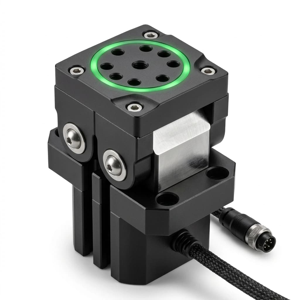
Treat robot mounting interface customization as a complete handling decision, not a stand-alone magnet purchase. The right choice depends on whether the workpiece can be held magnetically, whether the robot motion keeps enough margin, whether the part releases cleanly, and whether the installation scope is clear enough for quotation.
Buyer fit: For integrators who need the magnetic gripper to arrive with a clear mechanical integration plan. Before comparing price, align the practical constraints below so the quote reflects the real automation cell instead of a generic catalog condition.
| Decision Area | Buyer Question | Practical Evidence |
|---|---|---|
| Workpiece fit | Can the magnetic poles contact enough real surface area under production conditions? | Send robot brand, model, flange standard (iso 9409-1), and bolt pattern dimensions plus photos or drawings of the pickup face. |
| Motion margin | Will the gripper hold through acceleration, rotation, off center pickup, and stop conditions? | Review mechanical interface because a correct mounting interface reduces commissioning rework. |
| Release behavior | Can the part release within the placement tolerance without residual magnetism, double pickup, or stack disturbance? | Define sample acceptance criteria around mechanical interface and record the release test result before batch release. |
| Interface scope | Are the flange, adapter, cable, connector, controller, and documentation assumptions included in the same RFQ? | Confirm robot flange and adapter drawing and list any custom mounting or control requirements before PO release. |
Start with representative parts, including the worst expected surface condition. Check pickup contact, peel risk, air gap, and any stacked-part behavior before approving the gripper concept.
Test the planned orientation, acceleration, tool center, cable route, and stop assumptions. A static lift is not enough when the cell includes fast motion or rotated handling.
Measure release timing, residual magnetism, placement tolerance, and repeatability across a small run. Use the result to freeze pole layout, interface, and quality-control notes.
The most common sourcing mistake is treating holding force as a fixed catalog value. In practice, adapter plate adds unexpected mass that pushes the tool stack over the robot payload limit. Include adapter plate, bolts, dowels, and cable clamps in the mass calculation from the concept phase. Another common issue is that tool center of gravity is offset, causing the robot to exceed moment limits on extended-reach motions. Calculate and document the tool center of gravity with the full EOAT assembly and verify against the robot moment capacity at the actual reach.
For a quote that can move from engineering review to procurement, include the workpiece file set, automation interface, cycle target, release requirement, quantity, destination, and any custom packaging or documentation needs. If those values are not final, mark them as assumptions so the quotation can separate confirmed scope from validation-dependent scope.
| Program Metric | Typical Range | Procurement Value |
|---|---|---|
| Mechanical interface | Configured from robot model and drawing review | A correct mounting interface reduces commissioning rework. |
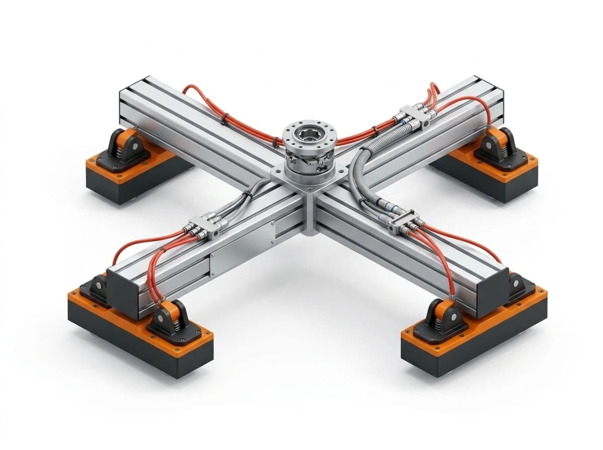
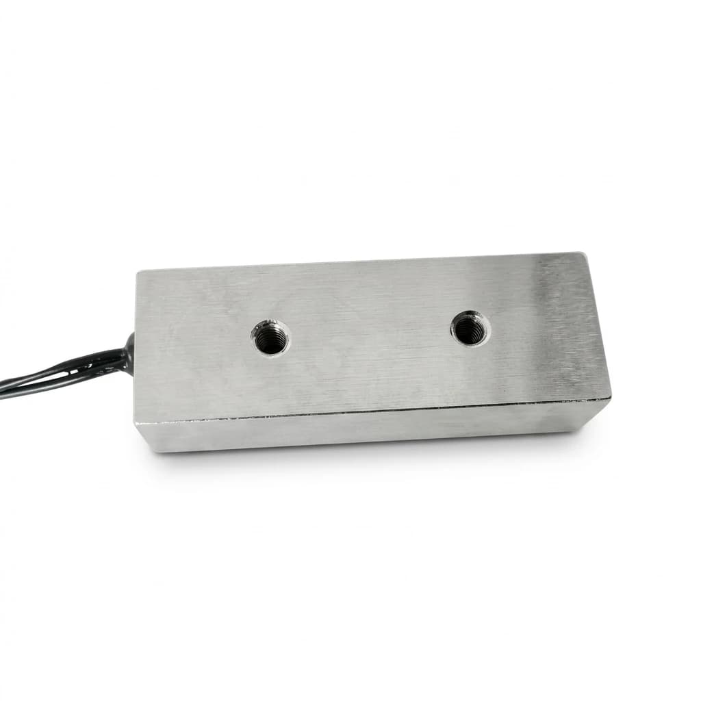
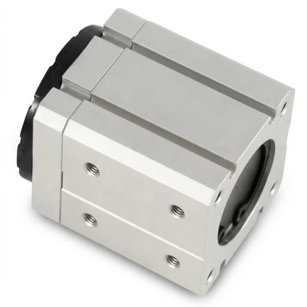
Either arrangement works. We can supply a complete gripper-with-adapter assembly, or provide the mounting drawing for the integrator to make their own plate. Define this in the RFQ.
We commonly supply ISO 9409-1 flanges and custom bolt patterns for ABB, FANUC, KUKA, Yaskawa, and UR cobots. Send the robot flange drawing for a compatibility check.
Yes, if the tool-changer supports the EOAT mass and provides the required power and signal pass-throughs. Send the tool-changer model and capacity data for review.
Inquiry Email
Include workpiece details, target holding force, quantity, and destination.