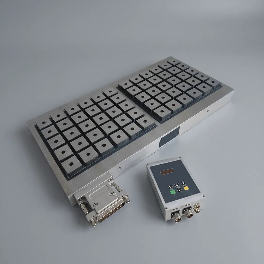
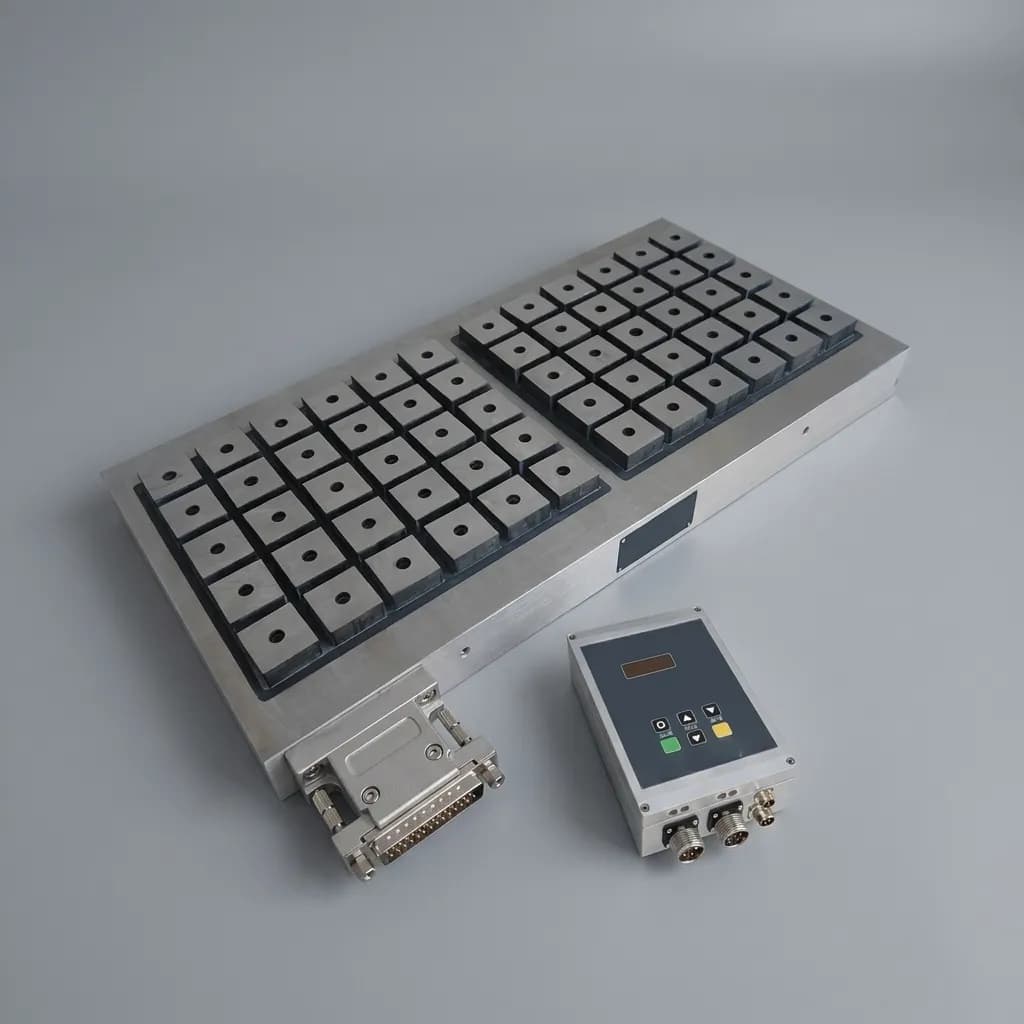
Safety Compliance and Fail-Safe Mechanisms in Magnetic EOAT: ISO 10218-2 and PL Buyer's Guide
A buyer's guide for procurement and engineering teams specifying fail-safe electro-permanent magnetic grippers against ISO 10218-2 and ISO 13849-1 expectations.
When specifying robotic End-of-Arm Tooling (EOAT) for heavy ferromagnetic payloads, the #1 priority for engineering and procurement teams is safety. Dropping a 50kg steel blank or a sharply edged stamped component due to a sudden power outage is a catastrophic risk that modern manufacturing cells must engineer out.
In the realm of magnetic gripping, the distinction between standard electromagnets and Electro-Permanent Magnets (EPMs) is the foundation of robotic safety compliance. With ISO 10218-2:2025 now published for industrial robot applications and robot cells, and ISO 13849-1:2023 current for safety-related parts of control systems, understanding how to source, specify, and integrate fail-safe magnetic EOAT is critical.
This comprehensive guide breaks down the application boundaries, procurement checklists, and compliance frameworks for fail-safe magnetic grippers. We will explore how EPMs interact with ISO standards, where their limits lie, and how to structure your RFQ to ensure your integrator delivers a system that is both compliant and highly productive.
Scope, Date, and Limits
This guide was reviewed on July 21, 2026 for global industrial buyers, robot integrators, and manufacturing engineers specifying magnetic grippers for ferromagnetic workpieces. It applies to electro-permanent magnetic EOAT in robot cells where power-loss retention, part-present sensing, shear-force margin, and risk-assessment evidence are part of supplier selection.
It does not replace a certified machine risk assessment, a local legal compliance review, or the purchased text of ISO standards. Treat it as a buyer-side specification framework: verify the final robot cell against the locally adopted edition of ISO 10218-2, ISO 13849-1, and any applicable regional or industry-specific rules.
1. The Core Hazard: The "Power-Loss Drop"
The most immediate danger in robotic material handling is the unintended release of a workpiece. In traditional vacuum gripping or standard electromagnetic gripping, a continuous supply of energy (compressed air or electrical current) is required to maintain the holding force.
If a factory experiences a sudden blackout, or if a cable on the robot arm is severed, standard electromagnets instantly lose their magnetic field. The payload drops immediately.
The Electro-Permanent Magnet (EPM) Solution
An Electro-Permanent Magnet (EPM) operates on a fundamentally different physical principle. It uses an electrical pulse—typically lasting less than a second—only to switch the polarity of internal magnets.
- Magnetization (ON): A short current pulse aligns the internal permanent magnets (often Alnico and Neodymium) so their magnetic flux is driven outward into the workpiece.
- Holding: Once magnetized, zero electrical power is required. The permanent magnets maintain a continuous, unyielding grip on the steel part.
- Demagnetization (OFF): A reverse current pulse realigns the internal magnets so the flux is short-circuited internally, releasing the part.
Because EPMs rely on permanent magnets for the actual holding phase, they are intrinsically safe against power loss. If power is cut mid-cycle, the magnetic flux remains exactly as it was. The workpiece stays securely attached to the robot.
2. Navigating ISO Standards for Magnetic EOAT
Procurement and engineering teams cannot simply buy an EPM gripper and declare their robot cell "safe." Industrial automation safety is holistic, governed by a series of interconnected ISO standards.
ISO 10218-1 and ISO 10218-2 (Robots and Robotic Devices)
These are the foundational standards for industrial robot safety. For new global projects, specify the current locally adopted edition; ISO lists ISO 10218-2:2025 as the published replacement for the withdrawn 2011 edition.
- ISO 10218-1 focuses on the robot manufacturer (the manipulator and controller).
- ISO 10218-2 focuses on the robot application and cell integration, including the end-effector (EOAT), workpiece, commissioning, operation, maintenance, and decommissioning assumptions.
Buyer-side safety expectation: the robot cell design must account for hazardous workpiece release during power loss, control failure, emergency stop, collision, commissioning, maintenance, and recovery scenarios. Confirm the exact requirement language in the purchased standard and in your regional adoption of ISO 10218-2.
By selecting an EPM gripper, procurement reduces a significant portion of the power-loss drop risk. However, integrators must still address how the robot behaves when an E-Stop is pressed (e.g., does the arm brake aggressively enough to cause the part to slide off via inertia?).
ISO 13849-1 (Safety-Related Parts of Control Systems - SRP/CS)
This standard defines how control systems should be designed to achieve a specific Performance Level (PL), ranging from PL a (lowest) to PL e (highest reliability).
When integrating a magnetic gripper, the safety logic must ensure the robot does not move unless the part is securely gripped.
- PL Requirement: If a risk assessment determines a high risk of injury (e.g., PL d required), the controller must reliably know the gripper's state.
- Sensing: Modern EPM grippers for robotic applications must include integrated sensors (e.g., inductive proximity sensors or magnetic flux sensors) to provide feedback to the PLC.
- Dual-Channel: For higher PL ratings, the signals confirming "Magnet ON" and "Part Present" may need to be dual-channel to prevent a single point of failure in the wiring from falsely signaling a safe state.
ISO/TS 15066 and Cobot Applications
ISO/TS 15066 remains a key reference for collaborative robot applications and is complementary to ISO 10218-2:2025. When using magnetic grippers on cobots, the primary concern shifts from just dropping the part to the hazards introduced by the part itself (sharp edges, mass) during a collaborative collision. Even if the gripper is fail-safe, the payload might mandate fencing or safety scanners.
For collaborative cells, use this article together with the cobot gripper selection guide so payload, flange, cable routing, and operator-interaction assumptions are reviewed before the EOAT is released for quotation.
3. Visualizing the EPM Safety Interlock
To achieve compliance, the EPM gripper must communicate bi-directionally with the robot controller. The safety case is not just "magnet ON"; it is a verified chain from robot command to controller pulse, gripper state, workpiece contact, and motion permission.
| Interlock Layer | What the Buyer Should Require | Why It Matters for Safety |
|---|---|---|
| Robot controller / PLC | Motion is blocked until grip confirmation is true. | Prevents the robot from accelerating before the part is secured. |
| EPM controller | MAG/DEMAG pulses are monitored and faulted if incomplete. | Confirms switching energy was delivered, not merely commanded. |
| Gripper sensors | Part-present and magnet-state feedback are available to the safety logic. | Avoids assuming the magnetic circuit closed on a real workpiece. |
| Workpiece verification | Flush contact, material fit, and air-gap assumptions are validated on samples. | Connects catalog force to the actual part condition. |
| Recovery behavior | E-stop, restart, manual recovery, and demagnetization steps are documented. | Prevents unsafe release during abnormal but foreseeable states. |
The PLC should only authorize the robot to accelerate if it receives the required safe-state feedback from the EPM controller and sensors, confirming both that the magnetization pulse was successfully delivered and that the part is physically detected against the gripper face.
4. Understanding Application Boundaries and Non-Power Risks
Procurement teams must understand that fail-safe against power loss does not mean infinite holding force. EPM grippers have strict application boundaries. If these boundaries are crossed, a catastrophic drop can still occur.
The Impact of Air Gaps and Coatings
Magnetic force decreases exponentially as the distance between the magnet face and the steel workpiece increases. This distance is known as the "air gap." Air gaps aren't always just empty space; they include:
- Paint, rust, or scale on the metal.
- Dirt, grease, or metallic chips accumulating on the gripper.
- Uneven or warped workpiece surfaces.
If a risk assessment assumes a clean, flat steel plate, but the actual process involves heavily scaled forgings, the gripping force may drop by 50% or more, invalidating the safety margins.
For the force calculation workflow behind these assumptions, see the magnetic gripper sizing guide for air gaps and coatings.
Dynamic Forces: Shear vs. Breakaway
- Breakaway Force: The force required to pull the part straight down, perpendicular to the magnet face.
- Shear Force: The force required to slide the part sideways across the magnet face. Magnetic shear force is typically only 20% to 30% of the breakaway force.
During a high-speed robot emergency stop (E-Stop), the robot arm decelerates violently. If the EOAT is oriented vertically, inertia will apply massive shear forces to the workpiece. If the shear force exceeds the friction and magnetic attraction, the part will slide off and become a dangerous projectile.
Mitigation Strategy Table
To maintain safety compliance, engineering must design mitigations for these non-power-loss risks.
| Hazard/Risk Category | Description of Failure Mode | ISO Compliance Implication | Mitigation Strategy for EPM Grippers | Sensor / Hardware Requirement | Safety Factor Requirement |
|---|---|---|---|---|---|
| Complete Power Outage | Facility loses all electrical power mid-transfer. | ISO 10218-2 (No hazardous release on power loss) | Intrinsic to EPM design. Permanent magnets maintain full hold. | None required for power loss itself. | Standard minimum 2x to 3x SWL. |
| Emergency Stop (E-Stop) | Violent deceleration causes shear force to overcome magnetic grip. | ISO 10218-2 (E-Stop must not cause hazardous release) | Ensure shear capacity exceeds max deceleration inertia. Use high-friction friction rings on magnet poles. | PLC calculates max robot acceleration limits based on payload. | 4x SWL (Safe Working Load) often recommended for high-speed shear. |
| Surface Contamination | Oil, rust, or dirt creates an unexpected air gap, dropping magnetic flux. | ISO 13849-1 (Unintended loss of safety function) | Regular automated or manual cleaning cycles. Flux monitoring. | Flux Sensor inside EPM to detect actual magnetic circuit saturation. | Derate holding force calculations by 30-50% for dirty environments. |
| Part Misalignment | Part is grabbed off-center, reducing magnet contact area. | ISO 10218-2 | Integrate mechanical centering guides on the EOAT. | Inductive Proximity Sensors to confirm 100% flush contact before moving. | Use multiple smaller magnets spread across the part instead of one large one. |
| Control Signal Failure | Severed wire falsely commands a demagnetization mid-flight. | ISO 13849-1 (SRP/CS Reliability) | Two-hand control logic or specific "Enable" interlocks. | Dual-channel safety relays. Controller requires complex pulse train to Demag, not just a simple high/low signal. | Aim for PL d or PL e architecture. |
| Catastrophic Collision | Robot crashes into a fixture, physically knocking the part off. | General Risk Assessment | Implement soft-axis collisions or secondary mechanical drop-stops for overhead critical paths. | Force/Torque sensors in robot wrist to instantly halt on impact. | Mechanical catch trays or safety netting below path. |
5. Procurement Checklist for Safety-Rated Magnetic Grippers
When issuing an RFQ (Request for Quotation) for a magnetic EOAT system, procurement and engineering must align to ensure the quoted hardware is capable of meeting safety standards. Do not just ask for "a magnet that lifts 50kg."
Use this checklist to evaluate supplier proposals:
- EPM Technology Verification: Confirm the technology is Electro-Permanent, NOT standard Electromagnetic. It must not require a UPS (Uninterruptible Power Supply) to maintain grip.
- Integrated Sensing Suite: Does the gripper include built-in inductive proximity sensors or flux sensors? (Required for PLC interlocks).
- Shear Force Data: Does the supplier provide documented shear force ratings, or only breakaway (pull) force? (Shear data is critical for robot acceleration planning).
- Air Gap Curves: Has the supplier provided force/air-gap curves to prove the magnet will safely hold your specific material condition (e.g., rusted or painted)?
- Controller Communication: Does the EPM controller support industrial safety protocols (e.g., PROFIsafe, CIP Safety, or dual-channel discrete I/O) to achieve the required Performance Level (PL)?
- Friction Enhancements: For high-speed applications, are friction rings or high-coefficient coatings applied to the magnet poles to resist sliding?
- Material Thickness Limits: Has the supplier confirmed the magnetic saturation depth? (If your steel is too thin, magnetic flux passes through and is wasted, reducing holding force).
6. Real-World Applications and the Bottom Line
The transition from vacuum or pneumatic gripping to Electro-Permanent Magnetic gripping is often driven by energy savings and maintenance reduction. However, the intrinsic safety of EPMs makes them the gold standard for handling heavy steel components like automotive frames, forging blanks, and structural steel beams.
If your team is still comparing gripping technologies, review magnetic gripper vs vacuum gripper for sheet metal before locking the EOAT concept.
By understanding that safety extends beyond "what happens when the lights go out," procurement teams can ask the right questions about shear forces, sensing, and control integration. A properly specified EPM gripper, integrated with respect to ISO 10218-2 and ISO 13849-1, provides unparalleled peace of mind on the factory floor.
7. Procurement and Engineering Decision Table
When specifying a fail-safe magnetic gripper, buyers must communicate specific parameters to suppliers to avoid compliance and performance failures. This decision table outlines the critical dimensions, boundaries, and communication fields required.
| Buyer Decision Point / Specification Dimension | Supplier Communication Field (What to Ask For) | Failure Risk if Ignored (Application Boundary) | ISO/Safety Context |
|---|---|---|---|
| Workpiece Material Thickness | Request magnetic saturation depth data and minimum thickness limits. | If steel is too thin, magnetic flux passes through (wasted), reducing breakaway force by up to 60%. | ISO 10218-2 (Unexpected hazardous release). |
| Surface Condition & Air Gap | Provide exact surface state (e.g., 2mm scale, oiled, painted) and request derating curves. | Paint or rust acts as a physical air gap. An uncommunicated 1mm gap can halve the holding force. | ISO 13849-1 (Unintended loss of safety function). |
| Dynamic Acceleration (E-Stop) | Specify maximum robot acceleration/deceleration (m/s²) and payload mass. | High inertia during E-Stop creates massive shear force, causing the part to slide off. | ISO 10218-2 (E-Stop behavior must not release part). |
| Controller Integration (SRP/CS) | Ask for communication protocol options (Profisafe, CIP Safety, discrete dual-channel). | Inability to safely read the "Magnet ON" and "Part Present" signals prevents PL d/e certification. | ISO 13849-1 (Performance Level requirements). |
| Workpiece Temperature | State maximum continuous operating temperature of the steel parts. | Magnets lose flux at high temperatures (Curie point limits). Internal coils can also overheat. | General Risk Assessment (Thermal degradation). |
| Cycle Time & Duty Cycle | Define MAG/DEMAG frequency and continuous running hours. | EPMs need cooling time between pulses. Too high a duty cycle burns out the EPM controller. | Operational Reliability (Non-safety failure mode). |
| Fail-Safe Mechanism Verification | Require confirmation that holding is 100% permanent magnet driven without UPS backup. | Misinterpreting an electromagnet with a battery backup as an EPM introduces battery failure risks. | ISO 10218-2 (Power loss safety). |
8. Frequently Asked Questions (FAQ)
Does an EPM gripper negatively impact our robotic cycle times compared to pneumatics?
A typical MAG or DEMAG pulse takes between 0.3 to 1.0 seconds. While vacuum cups might engage slightly faster, the elimination of mechanical clamping time often results in a net-zero impact. Buyers should ask suppliers for exact pulse durations for their specific EOAT size.
How do we verify the actual holding force on our specific, oily workpieces before integration?
You should mandate a factory acceptance test (FAT) or send sample workpieces to the EPM manufacturer. They can use load cells to generate an empirical force/air-gap curve specific to your part's alloy, surface roughness, and oil film.
Can we run an EPM gripper directly off the robot's 24V wrist supply?
Generally, no. EPMs require high-current pulses (often 400V or high-amperage 24V/48V via dedicated capacitors) to switch the magnetic polarity. You typically need to route a dedicated power cable down the robot arm from a separate EPM controller cabinet.
Is a secondary mechanical catch always required for overhead EPM lifting?
Not always, but it heavily depends on your specific risk assessment. If a part drop could injure personnel and the application involves high dynamic shear risks, a secondary catch might be required. However, for fully fenced, automated cells without human access beneath the payload, the EPM's fail-safe holding is usually sufficient.
References / Sources
- ISO 10218-2:2025 - Robotics — Safety requirements — Part 2: Industrial robot applications and robot cells. Current ISO page for robot application and cell integration safety. View on ISO.org
- ISO 13849-1:2023 - Safety of machinery — Safety-related parts of control systems — Part 1: General principles for design. Current ISO page for Performance Level (PL) design principles. View on ISO.org
- ISO 10218-2:2011 - Withdrawn previous edition of Robots and robotic devices — Safety requirements for industrial robots — Part 2: Robot systems and integration. Use only as historical context when reviewing older specifications. View on ISO.org
Ready to specify a fail-safe magnetic gripping solution for your robotic cell? Our engineering team supports ISO-aligned EOAT specification, providing full air-gap analysis, shear force calculations, and integration support. Contact our engineering team today with your robot model, workpiece drawings, surface condition, cycle target, and required PL so we can review the magnetic EOAT assumptions before quotation.
Author

Categories
More Posts
High-Temperature Magnetic Grippers: Sizing and Procurement for Hot Forging
High-temperature magnetic grippers sizing guide for hot forging: compare EPM safety, payload derating, duty cycles, cooling options, and RFQ inputs for buyers.
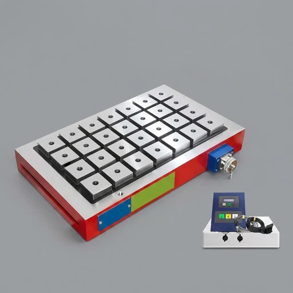
Magnetic Gripper Residual Magnetism and Demagnetization
Guide for engineers and buyers on why parts stick to magnetic grippers, how active demagnetization works, and how to define release acceptance criteria.
Smart Magnetic Grippers: IO-Link Integration and Procurement TCO
Evaluate smart magnetic grippers with IO-Link for TCO, wiring, diagnostics, and RFQ scope. Use the checklist before choosing standard or smart EPM tooling.