Magnetic Grippers for Cylindrical and Curved Workpieces: V-Block Pole Shoes, Pipe Wall Saturation, and Roll Moment Sizing
Size magnetic grippers for pipes and shafts: compare V-block pole shoes, screen wall saturation and roll torque, request a drawing-based engineering review.
Published and reviewed: November 2, 2026. Scope: Global engineering and procurement guidance for robotic magnetic handling of cylindrical, tubular and curved ferromagnetic workpieces.
Magnetic grippers for cylindrical parts need a contact profile suited to the diameter, a capacity assessment for the actual material and minimum pipe wall, and separate checks for pull-off, axial slip and roll torque. Start with supplier-approved V-block or radius-matched pole shoes. A flat-plate catalog rating cannot establish a safe pipe or shaft payload.
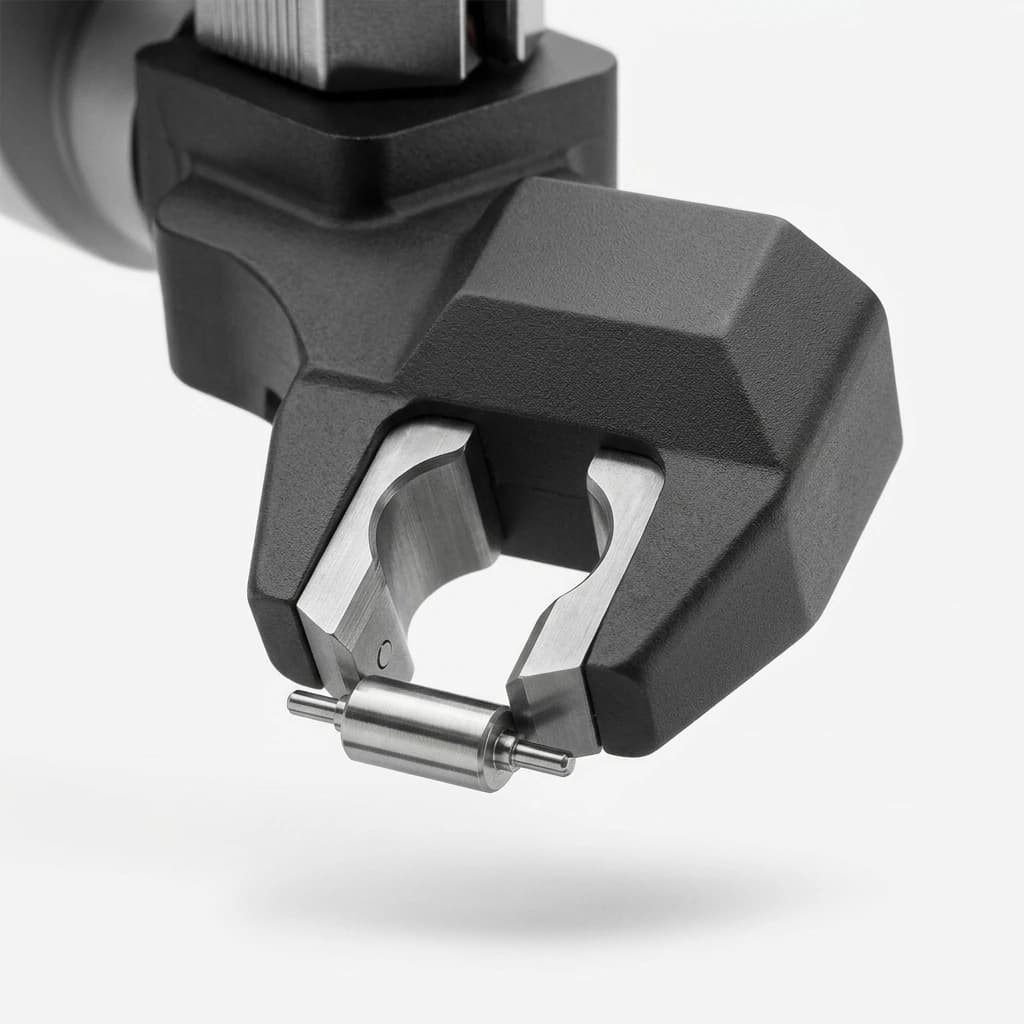
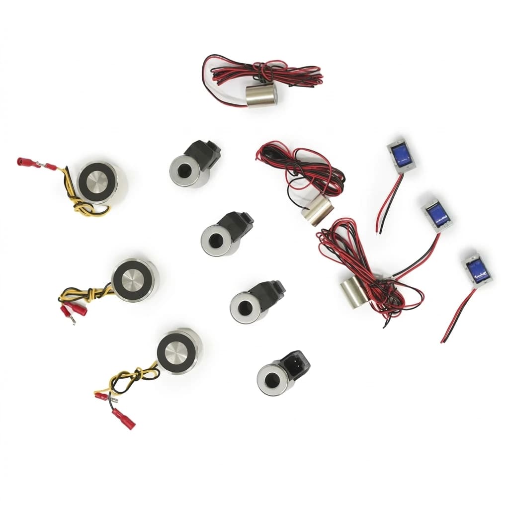
This guide provides a selection table, reproducible screening calculations and an RFQ checklist for engineers and buyers. The calculations are illustrative mechanics and magnetic-circuit estimates, not measured product performance or lifting approval. They exclude machining forces unless separately specified. The cover image illustrates shaped-jaw tooling; it is not evidence of a magnetic circuit or a tested load rating.
Have a part drawing ready? Request a cylindrical-part tooling review with the diameter range, minimum wall, material and robot motion profile.
1. Why Flat-Plate Ratings Do Not Transfer to Round Stock
A flat pole on a round surface has a narrow region of close contact, with increasing gaps to either side. For a cylinder of radius R, the geometric gap at lateral distance x from a tangent plane is:
g(x) = R - sqrt(R² - x²)
g(x) ≈ x² / (2R), when |x| is small compared with R
The widening is approximately quadratic near the tangent, not exponential. Pole spacing, surface roughness, coatings and scale also affect the magnetic circuit. A large diameter with suitable poles may behave differently from a small shaft under the same gripper.
The ideal magnetic-pressure estimate is:
F ≈ Bn² A / (2 μ0)
μ0 ≈ 1.257 × 10^-6 H/m
Here Bn is normal flux density in tesla, A is active area in square metres and F is force in newtons. This assumes a reasonably uniform, normal field at the evaluated gap. Curved contacts have a nonuniform field; neither the apparent shoe area nor the magnet's internal flux density can simply be inserted to predict capacity. Field modelling or supplier data must address the real geometry.
Do not apply a universal percentage reduction to a flat rating. Ask for the actual round-stock diameter, wall, air gap and shoe combination behind the quoted capacity.
2. V-Block Pole Shoes: Better Contact and Lateral Location
Prismatic V-shoes provide two seating regions for a circular section. Radius-matched shoes can provide broader contact over a narrower diameter range. Both need an approved magnetic path through the workpiece between opposite poles.
The diagram shows contact geometry, not a measured flux map. For an ideal symmetric V with included angle θ, the contact chord is w = 2R cos(θ/2). A 90-degree V gives about 1.414R; a 120-degree V gives R. This spacing is not a torque rating.
A 90-degree V forms a deeper cradle; a 120-degree V is shallower. Select the angle using the minimum and maximum diameters, both-face seating, pole coverage and surrounding clearance. There is no universal diameter band for either angle. Confirm that the smallest part cannot bottom in the recess and that the largest still seats on both intended faces.
Important distinction: a V locates a cylinder laterally, but a perfectly circular shaft can still spin in it. Contact normals pass through the circle's centre and do not, by themselves, provide a restoring couple about its own axis.
For a concrete supplier limitation, SCHUNK's EGM manual, sections 3.8 and 5.4 permits pole extensions on specified bipolar variants and warns of capacity reductions up to 75%. That is an EGM accessory limit, not a general V-shoe derating curve.
3. Hollow Pipes vs. Solid Shafts: Screening Wall Saturation
A pipe with the same OD as a solid shaft has less steel available for the return flux. Local saturation, leakage and the shoe interfaces can limit force. Solid stock can also saturate near a small pole; a solid core does not guarantee full catalog capacity.
A useful first screen for one identified wall-flux path is:
A_path ≈ t × L
B_wall ≈ Φ_path / (t × L)
t is minimum wall thickness in metres, L is effective axial path length in metres and Φ_path is flux through that path in webers. Obtain flux and path assumptions from the supplier or a magnetic model. Do not assume two equal circumferential return paths: their reluctances can differ substantially.
Illustrative arithmetic, not a pipe rating: assume one path carries 0.12 mWb = 0.00012 Wb over L = 40 mm. At t = 2.5 mm, the estimated density is 0.00012 / (0.0025 × 0.040) = 1.2 T. At t = 1.0 mm, the same assumed flux would imply 3.0 T, signalling that the assumed flux needs reassessment against the material's B–H curve. Actual flux redistributes as the material saturates.
This screen does not convert thickness linearly into holding force. Even a simplified pressure model depends on flux density squared, while contact geometry and leakage change with thickness. Request a tested capacity curve or application validation for the minimum wall, material condition and shoe geometry.
Plan representative sample validation before using a pipe-wall screen to approve tooling.
4. Pull-Off, Axial Slip and Roll Moment Sizing
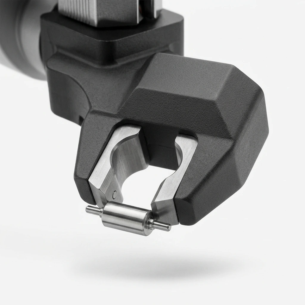
Illustrative shaped-jaw tooling image. It does not establish the actuation method, magnetic pole layout or tested holding capacity.
Separate three questions: can the part pull away, slide along its axis, or spin about its axis? Also evaluate pitch and yaw moments that peel one end away, especially on long stock. A pull-off test alone does not answer the other questions.
Roll demand: include angular acceleration and eccentricity
For conservative, aligned worst-case contributions about the cylinder axis:
M_roll,demand ≈ I_axis |α| + m |a_perp| e + m g e_gI_axis is mass moment of inertia about that axis in kg·m²; α is angular acceleration in rad/s²; m is mass in kg; a_perp is transverse acceleration in m/s²; and e and e_g are perpendicular lever arms in metres for inertial and gravity forces. The result is N·m. For a centred, uniform cylinder, translational acceleration through its centre does not itself create own-axis spin torque. Offsets, attached features and angular acceleration can do so. Resolve actual vectors and moments for each robot pose and stop case rather than assuming these maxima always coincide.
Roll resistance: friction or a positive feature
For a smooth circular part, an ideal Coulomb-friction screen is:
M_spin,ideal ≈ R × Σ(μ_i N_i)
F_axial,ideal ≈ Σ(μ_i N_i)
N_i is the actual compressive normal contact force at contact i, and μ_i is the friction coefficient for the actual surface condition. Do not substitute a flat-plate pull-off rating for the sum of V-contact normal forces. Oil, coolant, wear and contact pressure can change friction. Axial and spin demands share the available friction; both ideal maxima cannot be claimed simultaneously. These equations exclude peeling and loss of contact.
Use a supplier-qualified combined load envelope or representative tests. If orientation must be maintained, consider an approved anti-rotation feature engaging a flat, keyway or other noncircular detail. An axial end-stop addresses axial movement; it does not automatically prevent spin.
Reproducible load example for an RFQ
Assume a uniform steel tube of mass 12 kg, OD 60 mm and wall 4 mm. Set R_outer = 0.030 m, R_inner = 0.026 m, angular acceleration 20 rad/s², transverse acceleration 8 m/s², and separate worst-case inertial and gravity offsets of 0.005 m. For this illustrative envelope:
I_axis = 0.5 × 12 × (0.030² + 0.026²) = 0.009456 kg·m²
M_roll = 0.009456 × 20 + 12 × 8 × 0.005 + 12 × 9.81 × 0.005
       = 1.258 N·m, approximately
In a horizontal-axis pose with the gripper above the part, an upward acceleration of 4 m/s² gives a normal separation demand of 12 × (9.81 + 4) = 165.7 N. Acceleration of 5 m/s² along the horizontal tube axis gives 60 N axial demand. These are load demands before acceptance margins, not a selected gripper capacity. Specify where they occur together and add other handling forces, emergency-stop peaks and tool/robot inertia checks. Ask the supplier to validate normal force, axial load and moment together.
5. Engineering Comparison Across Seven Workpiece Profiles
Use this table to define the required evidence. No row supplies a universal capacity percentage or safety factor; both depend on the actual part and approved tooling.
| Workpiece profile | Main selection risk | Candidate tooling | Data required before selection | Validation priority |
|---|---|---|---|---|
| Solid low-carbon shaft | Spin and changing contact with diameter | Supplier-approved V-shoes | OD tolerance, finish, inertia and acceleration | Combined pull-off, axial slip and spin torque |
| Heavy-wall seamless pipe | Treating OD as proof of capacity | V-shoes or radius-matched shoes | Minimum wall, grade, ovality and mass | Capacity on the thinnest permitted wall |
| Thin-wall structural tube | Local saturation, ovalization and peeling | Application-specific pole layout or alternative grip | Wall tolerance, seam location and distortion limit | Flux feasibility and dimensional checks before transfer trials |
| Bearing outer ring | Residual magnetism and surface damage | Approved ID or OD tooling | Heat treatment, bore access and residual-field limit | Release, residual field and surface inspection |
| Camshaft or crankshaft | Eccentric load and asymmetric contacts | Matched contour or multiple supported contacts | CAD geometry, centre of gravity and pose-dependent inertia | Tipping and spin moments across the full path |
| Hexagonal steel bar | Orientation error at pickup | Flat poles on a defined flat, with locating features | Across-flats tolerance and pickup orientation | Seating confirmation and rotation under motion |
| Hydraulic cylinder barrel | Oil-driven slip and damage to finished surfaces | Approved contour tooling with an axial restraint if needed | Oil condition, wall, finish and access restrictions | Wet-surface slip and marking tests |
6. Pole Shoe Materials, Gaps and Mounting
Start with the magnet manufacturer's approved pole-shoe material and drawing. Soft, low-carbon steel is a common starting point, but grade names alone do not specify permeability, coercivity, wear behaviour or release performance. Hardened tool steels and wear treatments need an application assessment rather than an assumed magnetic equivalence.
Do not treat 304 or 316 stainless as reliable magnetic workpieces based on a hand-magnet response. Processing can change magnetic response; the exact grade and condition still need confirmation.
For custom shoes, obtain approval for:
- Mounting and contact faces: flatness, finish, cleanliness and permitted gaps at both interfaces; do not apply a universal force loss per 0.1 mm.
- Coatings and inserts: thickness and placement in the magnetic path. A friction pad or nonmagnetic protective layer may improve one aspect while reducing attraction through added gap.
- Fasteners: material, strength, engagement, torque and positioning from the OEM drawing. Nonmagnetic screws are not a universal requirement.
- Release and service life: residual-field limits, chip accumulation, wear inspection and replacement criteria under the actual coolant and temperature conditions.
7. Internal-Diameter vs. External-Diameter Gripping
An engineered ID tool may keep the outside surface accessible on rings or hollow cylinders. It still requires sufficient bore access, wall section and approved pole contact. Thin walls can deform under local magnetic loading, so ID gripping does not eliminate distortion or saturation.
Check insertion clearance, collision avoidance, swarf removal and release access. Compare magnetic ID tooling with mechanical mandrels using the actual transfer requirements. Neither approach automatically leaves both end faces accessible.
A robot transfer gripper is not automatically a workholding chuck for turning or grinding. Cutting loads, accuracy and clamping suitability require separate approval.
8. Standards Scope and Acceptance Margins
For hoist-mounted equipment, ASME B30.20-2025 addresses below-the-hook devices. The NEN record for EN 13155:2020+A1:2025 covers non-fixed attachments for cranes, hoists and manually controlled load manipulators, including lifting magnets, and lists a 2026 correction. That scope must not be extended automatically to every industrial robot gripper.
The public records establish scope and edition, not the full clauses or a universal robotic safety factor. Obtain the applicable edition and identify the device category, jurisdiction and installation requirements with the responsible integrator. Do not infer certification or a robot payload from a quoted 3:1 or 5:1 flat-plate breakaway ratio.
For the robot cell, agree margins against actual combined force and moment demands, the supplier's permissible loads, process variation and the machine risk assessment. A standards test ratio, operating margin and acceleration multiplier are different quantities.
Electro-permanent magnetism can retain the magnetized state without continuous power; SCHUNK's EGM product description describes pulse switching and retained holding. This does not, by itself, make the complete cell fail-safe. Confirm the response to incomplete seating, power or air loss, sensor faults and emergency stops for the chosen hardware.
9. Sizing and Procurement RFQ Checklist
Provide the following before requesting a tooling quotation. Record unknowns explicitly so they become validation tasks rather than hidden assumptions.
Workpiece envelope
- Minimum and maximum OD, ovality, straightness and usable contact length.
- Minimum pipe wall including tolerance, seam position and local thinning.
- Length, maximum mass, centre of gravity and relevant inertias.
- Material grade, heat treatment and magnetic suitability of the actual condition.
- Minimum and maximum part/tool temperature and switching duty cycle.
- Surface finish, scale, coatings, oil or coolant and permitted marking.
Robot motion and installation
- Robot model, EOAT mass, flange interface, payload and wrist inertia limits.
- Peak acceleration and angular acceleration, poses and emergency-stop load data.
- Normal, axial, spin and peeling demands, including combinations.
- Clearance, collision envelope, pickup support and deposit stability.
- Cycle time, chip control, inspection access and maintenance conditions.
Tooling and acceptance evidence
- Approved shoe profile, material, mounting drawing and diameter/wall envelope.
- Actuation type and documented power/air-loss behaviour.
- Seating and part-presence signals, and how insufficient holding is detected; presence alone does not prove capacity.
- Safety functions and required control performance derived from the cell risk assessment.
- Application-specific capacity evidence, combined-load limits and agreed acceptance margins.
- Trial plan: representative worst-case parts; instrumented pull-off, axial slip and spin tests; guarded motion/stop trials; release and residual-field checks.
Record test conditions, sample identities, repetitions and results. No physical test results are claimed in this guide. Commission only after the responsible integrator approves the evidence and remaining limits.
10. Technical Sources and Their Limits
Source records checked November 2, 2026. Standards summaries establish scope; the vendor material applies to its own products. The arithmetic above is an explicitly simplified engineering screen, not a formula prescribed by these standards.
- ASME — B30.20-2025: Below-the-Hook Lifting Devices. Primary standards-body record for hoist attachment scope. Limit: the public summary does not substantiate clause-level design factors or robotic compliance claims.
- NEN — EN 13155:2020+A1:2025. National standards-body record, including a listed 2026 correction. Limit: scope and edition information is not an assessment of a particular robot cell.
- SCHUNK — EGM magnetic gripper. Manufacturer description of electro-permanent handling and switching. Limit: it gives no transferable rating for custom cylindrical tooling.
- SCHUNK — EGM Assembly and Operating Manual, 389539, version 03.00, August 21, 2023. See printed pages 23, 25–27 and 35 for pole extensions and workpiece-dependent holding. Limit: model-specific instructions; confirm the revision for the supplied hardware. This SCHUNK-authored PDF is hosted on its asset CDN.
11. Frequently Asked Questions
Why do flat magnetic grippers lose holding force on round bars or pipes?
Curvature reduces close contact and adds air gaps around the tangent region. The loss depends on diameter, pole layout, alloy, surface condition and wall thickness; there is no universal percentage derating. Use the supplier's round-stock rating or tests on the actual part.
How does pipe wall thickness affect magnetic gripper selection?
A thin wall restricts the steel cross-section carrying magnetic flux and may saturate locally. Outer diameter alone cannot establish capacity. Specify minimum wall thickness and material condition, then obtain capacity data for that pipe and pole-shoe combination.
Do V-block pole shoes prevent a cylindrical part from spinning?
V-shoes help locate a cylinder laterally and improve contact, but a smooth circular section can still rotate about its own axis. Spin resistance depends on friction, contact normal forces and any positive anti-rotation feature. Validate roll torque separately from pull-off force.
Should V-block pole shoes use a 90-degree or 120-degree angle?
A 90-degree included angle forms a deeper cradle; a 120-degree angle is shallower. Neither angle has a universal diameter range or torque rating. Check contact on both faces, pole coverage, tool clearance and supplier-approved capacity across the actual diameter tolerance.
What steel should be used for custom magnetic pole shoes?
Start with the gripper manufacturer's approved soft magnetic material, often a low-carbon steel. Grade, heat treatment, wear protection and mounting details affect flux and release. Do not substitute hardened tool steel or nonmagnetic inserts without approval and a new capacity assessment.
Can an internal-diameter magnetic gripper handle rings or hollow cylinders?
An engineered ID tool can leave the outside surface accessible when bore clearance, wall thickness and pole contact are adequate. It does not remove saturation, distortion or slip risks. A transfer gripper must not be treated as a machining chuck without separate approval.
What safety factor is required for robotic magnetic handling of round parts?
There is no universal robotic safety factor derived from a flat-plate breakaway rating. Establish applicable standards and supplier limits, calculate normal, axial and moment demands including stopping loads, and agree acceptance margins through the machine risk assessment and representative testing.
12. Engineering Review and Integration Support
Use the RFQ checklist to compare suppliers on application evidence, not the largest flat-plate force number. A useful proposal identifies the shoe drawing, material and wall envelope, combined-load limits and the validation still required.
- Review the cell layout and load planning through our machine tending solutions.
- Confirm tooling attachment details through the robot mounting interface guidance.
- Discuss V-shoes, contoured contacts and restraints through custom EOAT integration.
- Define representative trials through sample validation and quality control.
Submit your part drawing and motion specifications to discuss tooling feasibility, the evidence needed for selection and a suitable validation plan.
Author

Categories
More Posts
Magnetic Grippers for CNC Machine Tending: Dual-Gripper EOAT, Swarf Ingress, Coolant Sealing, and Chuck Clearance
Select magnetic grippers for CNC machine tending: compare dual EOAT, swarf control, coolant sealing and chuck clearance. Use the checklist to plan your RFQ.
Sheet Metal Destacking Automation: Magnetic Grippers, Sheet Fanners, and Zero Double-Blank Prevention
Plan sheet metal destacking with magnetic grippers, sheet fanners and double-sheet detection. Compare tooling, prepare RFQs and define sample acceptance tests.
High-Temperature Magnetic Grippers: Sizing and Procurement for Hot Forging
High-temperature magnetic grippers sizing guide for hot forging: compare EPM safety, payload derating, duty cycles, cooling options, and RFQ inputs for buyers.