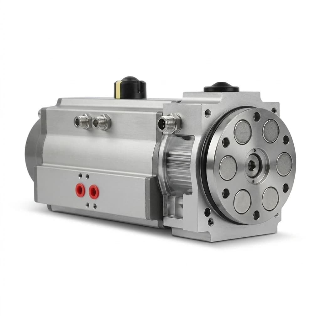
Magnetic Grippers for CNC Machine Tending: Dual-Gripper EOAT, Swarf Ingress, Coolant Sealing, and Chuck Clearance
Select magnetic grippers for CNC machine tending: compare dual EOAT, swarf control, coolant sealing and chuck clearance. Use the checklist to plan your RFQ.
Published and reviewed: October 29, 2026. Scope: Global engineering and procurement guidance for automated CNC lathe and milling tending with ferromagnetic workpieces.
Magnetic grippers for CNC machine tending can hold a billet by its end face, leaving its outer diameter available for chuck jaws. A dual-gripper end-of-arm tool (EOAT) can pre-stage the next blank while removing the finished part. Select this approach only after verifying wet holding force, swarf removal, coolant compatibility, and the clearance of both loaded heads.
This guide combines the supplier documents linked below with a transparent sizing example and an RFQ checklist. The calculations are illustrative engineering screens; they are not measured production results or certification of a particular gripper. Aluminum, copper, brass, and normally nonmagnetic 304/316 stainless are outside the intended scope. Confirm magnetic response and holding force for the actual material grade and condition.
For an application review, send your part drawing, coolant specification, and chuck envelope. The acceptance questions below help define the evidence to request before ordering.
The Dual-Gripper Spindle Advantage: Cycle Time Economics
A single head may need to remove the finished part, visit the outfeed, pick a blank, and return to the machine before cutting resumes. Two heads can move the outfeed and infeed work into the machining window. Magswitch describes multi-head machine-tending designs and customized pole shoes; it does not establish a universal exchange time for your cell.
Compare complete cycles using parts per hour = 3600 / (cutting time + exchange time). For an illustrative assumption of 90 seconds cutting time, reducing exchange time from 28 to 12 seconds changes theoretical output from 3600 / 118 = 30.5 to 3600 / 102 = 35.3 parts/hour, a 15.7% increase. These are calculated values, not a customer case study. Availability, scrap, cleaning, and tool changes reduce actual output; the calculation is not an OEE measurement.
The 180-Degree Indexing Dual-Gripper Architecture
- During machining, pick a raw billet on Head B and wait outside the machine's permitted access boundary.
- After spindle-stop and access interlocks permit entry, place empty Head A against the finished part. Verify the validated gripping condition before commanding chuck release.
- Extract along the chuck axis far enough to clear jaws, locators, and ejectors. The required distance comes from the machine drawing and trial sequence.
- Index the robot wrist or rotary unit only inside a verified swept envelope. If both loaded heads cannot rotate inside the machine, retract outside before indexing.
- Seat the blank using Head B. Verify seating and chuck clamping before releasing magnetic hold; verify release before retracting.
- Exit, close the enclosure, and resume cutting only after the cell interlocks are satisfied. Unload Head A and prepare the next blank during machining where the layout permits.
Measure door, chuck, cleaning, sensing, and index delays together. Added EOAT mass and inertia can require slower motion and offset the travel saved.
The diagram is a conceptual sequence, not a dimensioned installation drawing or evidence of a tested cycle time.
5-Sided Workpiece Accessibility vs Mechanical 3-Jaw Grippers
SCHUNK's magnetic-gripping overview describes five-side access and pulse-switched holding. End-face contact can avoid fingers around the billet OD, but the housing, pole extensions, cables, and second head still occupy space. Confirm that the contact face remains available after machining and that a smaller or thinner part still bridges the required poles.
For chuck clearance, overlay the gripper CAD and both workpieces on the chuck at its open and closed jaw positions. Check insertion depth, locator and ejector travel, turret and tailstock positions, door aperture, and the entire wrist-index sweep. Include assembly tolerances and cable motion; establish clearance margins with the machine integrator rather than adopting a universal distance.
| Evaluation metric | Mechanical gripper | Vacuum tooling | Magnetic EOAT | Evidence to request |
|---|---|---|---|---|
| Contact geometry | Fingers need OD or ID space | Needs a suitable sealing area | Needs adequate magnetic contact and pole coverage | CAD check for the smallest and largest parts |
| Wet handling | Contact and guide protection depend on design | Fluid ingestion may require separation and suitable cups | Oil film and chips can reduce available grip | Wet pull-off and shear tests on actual parts |
| Swarf | Chips can lodge in jaws or guides | Chips can disturb seals or enter the circuit | Ferrous chips can adhere to poles | Cleaning trial with representative swarf |
| Part-family changes | May need finger changes or adjustment | May need cup pattern changes | May share a pole face if force and geometry permit | Validation for each material and thickness |
| Power or air loss | Retention depends on the complete mechanism | Retention depends on circuit and leakage | An EPM can retain its magnetic state without power | Retention and stopping tests for the assembled cell |
| Surface quality | Jaw pressure can mark finished surfaces | Cup contact can leave marks | Chips or pole contact can mark finished faces | Inspection against the drawing's finish requirements |
| Exchange time | Single or dual configurations are possible | Single or dual configurations are possible | Dual heads can remove intermediate trips | Complete cycle timing with payload and interlocks |
Review robot magnetic gripper options and custom robot gripper layouts against these acceptance criteria.
The Swarf Challenge: 4-Tier Chip Mitigation Engineering
A chip between the pole and billet creates a gap, can tilt the part during chuck insertion, and may scratch the finished face. The holding-force reduction depends on the actual gap, pole geometry, material, and thickness; a single percentage does not describe every tool.
1. Specify Pole Geometry for the Actual Workpiece
Ask the supplier to evaluate flux paths, minimum part thickness, and attraction to nearby chuck jaws. Shallow-field designs can be useful for thin parts, but a universal pole pitch or fixed penetration depth cannot prove isolation from surrounding steel. Validate the selected head with the chuck arrangement present.
2. Validate Air Purge Inside the Enclosure
Aim an approved nozzle across the accessible part or pole face. Select pressure, flow, distance, and pulse duration within the nozzle, gripper, and machine limits. Test where chips and coolant land; a strong blast can move contamination into locators or connectors. Clean exposed pole faces between picks, with loose debris contained by the enclosure.
3. Verify Release Before Demagnetizing or Cleaning
Support the part in the clamped chuck or outfeed nest before issuing a release command. An EPM needs its specified switching pulse; removing supply power does not command release. A release pulse is not a guarantee that the workpiece is demagnetized to a particular field limit. Measure residual field if downstream grinding, inspection, or welding requires it.
4. Add an Accessible Cleaning Station When Needed
If stringy swarf survives purge, trial a guarded wiper or brush station with a supplier-approved contact material. Verify that cleaning does not damage pole coatings or introduce debris into the next pick. Define inspection frequency and a stop condition for chips that cannot be cleared automatically.
Use the residual magnetism and demagnetization guide to frame release acceptance questions; obtain model-specific controller instructions before selecting a sequence.
Wet CNC Machining: Friction, Shear Forces, and Safety Sizing
Catalog pull-off force is not the same as allowable tangential load. The SMC MHM catalog, printed pages 3–4 and 6, distinguishes orientation, acceleration, friction, part thickness, and full-surface low-carbon-steel reference conditions. MHM is a pneumatically switched magnet, so its force data must not be transferred to an EPM model.
For a first screen with no external separating load, use F_tangential,max = mu_test × F_normal,effective. Here mu_test is the measured friction coefficient for the actual pole/pad, part finish, and coolant. F_normal,effective is the available magnetic pull-off force at the actual contact condition. Neither a universal wet friction coefficient nor a generic air-gap multiplier is defensible.
Worked Example: A Vertical Contact Face
Assume an 8 kg billet, a vertical pole face, and 4 m/s² upward acceleration parallel to that face. For this illustration only, assume mu_test = 0.15 and a screening multiplier S = 3. The multiplier is an input, not a prescribed safety standard.
- Tangential demand:
F_t = 8 × (9.81 + 4) = 110.48 N. - Effective normal holding requirement for this shear screen:
F_normal,effective >= S × F_t / mu_test = 2209.6 N, approximately 2.21 kN. - If supplier evidence establishes that the actual contact condition retains 60% of that model's catalog force, the corresponding catalog screen is
2209.6 / 0.60 = 3682.7 N, approximately 3.68 kN. The 60% is an illustrative assumption, not measured derating data.
This example omits normal separation, off-center moments, peeling, extraction resistance, and combined loading. Analyze these separately, including stopping loads, before approval. With an external separating load, the full magnetic force is not available as friction-producing contact force. A positive locator can change the load path, but its strength and clearance also require validation.
| Workpiece / operation | Contact uncertainty | Required test or document | Acceptance decision |
|---|---|---|---|
| Saw-cut lathe blank | Burrs, scale, and partial contact | Pull-off and shear tests on the roughest allowed face | Reject or prepare faces that exceed validated gap conditions |
| Finish-turned shaft | Smooth oily face and offset center of gravity | Wet slip and moment tests on the finished condition | Reduce acceleration or redesign contact if margin is inadequate |
| Cast-iron flange | Material-dependent magnetic response and dust | Tests on the specified cast grade and thickness | Use measured force rather than steel catalog values |
| Milled manifold block | Holes, pockets, and trapped coolant | Pole coverage drawing and release trial | Confirm enough supported contact and repeatable release |
| Bearing ring | Narrow annular land and interrupted flux path | Pole-shoe review and representative ring trials | Approve only the validated diameter and wall-thickness range |
| Thin flange | Limited thickness and possible attraction through the part | Minimum-thickness force and nearby-steel checks | Change pole design or handling method if either test fails |
For further background, see the magnetic gripper sizing guide. For this CNC application, replace generic coefficients with supplier curves and representative wet-part tests.
Sealing and Reliability: IP67/IP68 and Coolant Compatibility
Specify the exposure before specifying the seal: coolant trade name, concentration, pH range, temperature, nozzle pressure and distance, spray direction, cleaning chemicals, and operating duration. Request written approval for the exact assembled gripper, sensors, connectors, and cable routing.
An IP67 or IP68 immersion rating alone does not demonstrate suitability for direct coolant jets or chemical exposure. Review the applicable test conditions and obtain evidence matching the installation. IEC's water-test standard overview distinguishes water exposure tests from corrosion testing; a water test cannot establish coolant compatibility.
A concrete exclusion matters more than a generic "sealed" claim: the SMC MHM-25D-X7400A manual, section 3.2 prohibits dusty environments and water or oil splashing onto that product. It is cited here as an environment limit, not as approval for a flooded CNC cell. The MHM catalog also notes that a water-resistant auto switch does not establish gripper water resistance.
Hardware Requirements to Agree with the Supplier
- Housing and coil protection: Document ingress protection, any potting or encapsulation, service limits, and the response to damage. Potting does not prove hermetic integrity of the assembled tool.
- Seal compatibility: Ask for compatibility evidence for the actual coolant and temperature. FKM, NBR, and other compounds have application-dependent limits; do not mandate one elastomer for every fluid.
- Pole coatings: Confirm corrosion and wear performance, repair limits, and the effect of coating thickness on magnetic contact. Specify finish requirements from the part and validated design rather than a generic plating thickness.
- Connectors and cables: Verify ratings in the mated installation, cable chemical compatibility, bending and torsion limits, and replacement intervals. A connector rating cannot establish the rating of the whole EOAT.
Engineering & Procurement Checklist for CNC Tending Tooling
Before issuing an RFQ or approving mechanical integration drawings for a magnetic CNC machine tending cell, project teams should verify every line item across the five critical engineering disciplines:
1. Workpiece Metallurgy and Contact Geometry
- What is the exact material grade (e.g., AISI 1045 carbon steel, 4140 alloy steel, ductile cast iron, or 400-series magnetic stainless)?
- Is the proposed magnetic contact zone flat, cylindrical, or stepped?
- What is the minimum and maximum workpiece diameter, thickness, and total mass?
- Does the part feature through-holes, keyways, or tapped holes across the magnetic contact area that reduce effective pole contact?
- What is the surface finish (Ra value) and scale condition of the incoming billet?
2. Machine Tool Enclosure and Chuck Kinematics
- What is the clear opening width and height of the CNC automatic door?
- What is the maximum Z-axis travel and tool turret clearance envelope inside the machine?
- Does the 3-jaw chuck or collet chuck have internal spring-loaded part-ejector pins that push against the gripper during unclamping?
- What is the required part insertion depth into the chuck jaws, and will the magnetic gripper housing clear the chuck body?
- Is there sufficient clearance for the robot to execute a 180° dual-head index inside the door frame, or must it retract outside before rotating?
3. Coolant, Swarf, and Purge Provisioning
- What type of cutting fluid is used (water-soluble synthetic emulsion, semi-synthetic, or straight oil)?
- Does the robot EOAT incorporate rated air-purge nozzles with a validated pressure and duration aimed at the magnetic pole shoes?
- Is an auxiliary air blast sequence programmed into the CNC controller to clear chips off the chuck face prior to part insertion?
- Does the cell include an external passive wiper brush station for handling long-chip turning operations?
4. Robot Payload Stack and Wrist Moment Limits
- Has the total EOAT weight been calculated: Base adapter plate + dual EPM magnetic modules + pneumatic indexer + valves/sensors + two fully loaded workpieces?
- Does the combined center of gravity (CoG) and moment of inertia (Jx, Jy, Jz) fall within the robot manufacturer's limits for the programmed path and stopping profile?
- Is the robot wrist flange standard compliant with ISO 9409-1 (e.g., ISO 9409-1-50-4-M6 or ISO 9409-1-100-6-M8)?
- Are pneumatic and electrical lines routed through a dress pack that prevents torsional snagging during repeated 180° wrist rotations?
5. Downstream Integration and Residual Magnetism
- Does the downstream process include magnetic particle inspection (MPI), cylindrical centerless grinding, balancing, or laser welding?
- What is the maximum allowable residual magnetism specification on the released part at defined measurement locations and probe stand-off?
- Does the chosen controller support the required release or demagnetization sequence, verified on the actual part?
- Do measured residual fields require an auxiliary demagnetizer for the downstream process?
- Are chuck-clamped, part-seated, gripper-state, and part-present signals separately validated, including fault recovery?
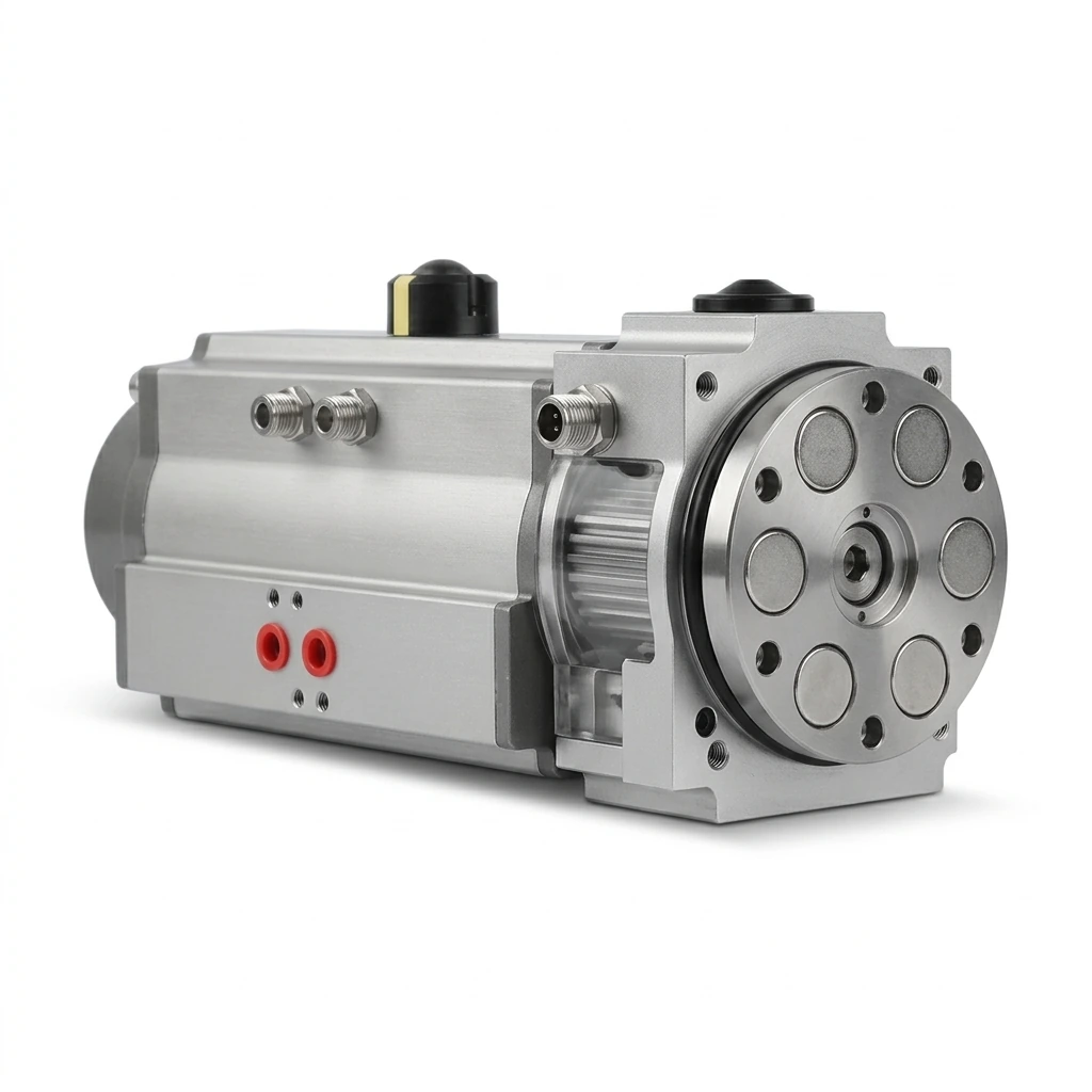
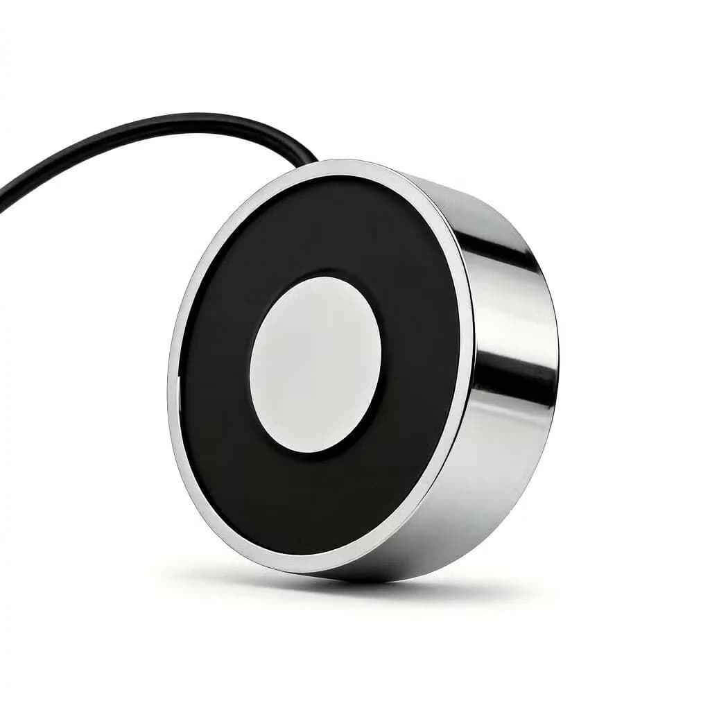
Illustrative magnetic tooling head. This image does not establish a dual-head layout, coolant rating, or validated machine installation.
Technical Sources and Their Limits
Sources checked October 29, 2026. Supplier statements apply to the identified products and conditions; none establishes this article's illustrative cycle or sizing values as measured results.
-
SCHUNK — Magnetic gripping — Explains EPM switching, power-loss holding, and five-side workpiece access. It does not approve every magnetic gripper for flooded machining.
-
Magswitch — Pick and Place/Machine Tending Industrial Automation — Describes multi-head tooling and customized pole shoes for machine tending. No universal cycle time is inferred.
-
SMC — MHM Series Magnet Gripper, CAT.ES100-131A — Printed pages 3–4 and 6 provide selection guidance and reference-force conditions; printed page 5 limits water-resistance claims. This is a pneumatic magnet series, not EPM test data.
-
SMC — MHM-25D-X7400A Instruction Manual, MHM-TF2Y020EN — Page 1, section 3.2 sets explicit environmental exclusions, including water and oil splash. Used here to illustrate a model-specific rejection criterion.
-
IEC — IEC 60068-2-18:2017, Water environmental tests — The official scope describes water-exposure testing and explicitly excludes corrosion testing. It is not a chemical-compatibility certificate or an IP approval for a gripper.
Frequently Asked Questions
How do you prevent ferromagnetic chips (swarf) from sticking to the magnetic gripper face?
Reduce chip pickup with an application-specific pole layout, approved air purge, and an accessible cleaning station. Clean exposed faces after the part is supported and the gripper is released. Validate the sequence with the actual chip shape; demagnetization alone will not remove tangled swarf.
Can a magnetic gripper load cylindrical billets into a 3-jaw lathe chuck without slipping?
It can, if the end face or contoured pole shoes provide adequate contact and the wet shear, pull-off, and moment margins are verified. Measure slip resistance with the actual coolant and stopping profile. End-face gripping can free the outer diameter, but housing and chuck-jaw clearances still require a CAD sweep.
Will the magnetic field couple into the CNC chuck or machine spindle and cause damage?
Stray attraction depends on pole design, part thickness, material, and distance to nearby steel. Request field or application test evidence for the actual chuck arrangement. There is no universal pole pitch or penetration depth that guarantees isolation from the machine.
Why choose Electro-Permanent Magnets (EPM) instead of conventional electromagnets for CNC tending?
An EPM uses electrical pulses to switch its holding state and can retain magnetic holding force without continuous coil power. That helps with power-loss retention, but does not establish safe stopping, adequate wet grip, or release verification. Check the specific controller and complete cell behavior.
How does a dual-gripper magnetic EOAT reduce CNC cycle time compared to a single gripper?
It pre-stages the raw billet on one head while the other removes the finished part, potentially avoiding an outfeed and infeed trip during spindle idle time. Savings depend on door motion, chuck handshakes, cleaning, wrist indexing, and added payload. Measure the complete exchange rather than assuming a universal cycle time.
What sealing protection is needed for cutting fluids and high-pressure coolant?
Specify the actual coolant, concentration, temperature, spray direction, pressure, and exposure duration. Obtain written approval for the assembled gripper, connectors, seals, and cables. An IP67 or IP68 label alone does not establish resistance to direct coolant jets or chemical compatibility; FKM is not a universal requirement.
How do we handle residual magnetism on precision parts heading to grinding or balancing?
Agree a residual-field limit and measurement method with the downstream process owner. Measure representative released parts at defined locations and probe stand-off. Check the selected controller’s release capability; add separate demagnetization if acceptance tests require it. Do not assume a universal gauss threshold or guaranteed EPM demagnetization result.
Plan Your CNC Machine Tending Automation
Use the checklist to define a sample test and an integration review before comparing purchase prices. Send the part material, CAD, minimum contact thickness, mass, coolant specification, chuck drawing, robot model, and target exchange sequence.
- Explore application requirements on our machine tending solutions page.
- Check flange and service-routing requirements in the robot mounting interface guide.
- Discuss brackets and pole shoes with our custom EOAT integration team.
- Agree wet holding, release, swarf, and clearance acceptance through sample validation and quality control.
Request a CNC Machine Tending Review with those inputs so the review can identify missing evidence and a practical validation plan.
Author

Categories
More Posts
Sheet Metal Destacking Automation: Magnetic Grippers, Sheet Fanners, and Zero Double-Blank Prevention
Plan sheet metal destacking with magnetic grippers, sheet fanners and double-sheet detection. Compare tooling, prepare RFQs and define sample acceptance tests.
High-Temperature Magnetic Grippers: Sizing and Procurement for Hot Forging
High-temperature magnetic grippers sizing guide for hot forging: compare EPM safety, payload derating, duty cycles, cooling options, and RFQ inputs for buyers.

Magnetic Gripper Residual Magnetism and Demagnetization
Guide for engineers and buyers on why parts stick to magnetic grippers, how active demagnetization works, and how to define release acceptance criteria.